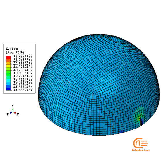
To model how the material changes due to damage, we need to define damage evolution. For this case, once the maximum principal stress exceed a value of 400 MPa. This has the advantage that the crack plane can be perpendicular to the direction of maximum principal stress making it solution dependent. In this case maximum principal stress (MAXPS damage) was used. In each case, damage is assumed to initiate when the stress/strain satisfy the input damage criteria.

For damage initiation, several criteria are available: maximum nominal stress/strain, quadratic nominal stress or maximum principal stress/strain. To model crack propagation in Abaqus, we need to describe the damage initiation and evolution behaviors. To illustrate the principle of XFEM, we used generic steel properties: E=210 GPa, ν=0.3, ρ= 7850 kg/m 3. Ideally the implant would be made of a CoCr or Ti6Al4V alloy, but fracture criteria are scarce. To accurately model the crack propagation path, a denser mesh would be needed for this part, but for illustration purposes, it should be enough. This was then partitioned so that we could obtain a hexahedral mesh on the part. The previous hip replacement geometry was used. More importantly, there are some advantages when it comes to the crack itself: 1) No need to specify the crack path and initial location 2) Mesh is generated independent of the crack 3) No need to partition the geometry at the crack location though the mesh density should be high enough. However, if we want to model bulk fracture and allow the crack to be located in the element interior, XFEM comes in handy.

Conventional fracture modeling only permits crack propagation along predefined boundaries.


 0 kommentar(er)
